This project shows you how to create an awesome music visualizer using an Arduino and an LED strip.
After building this project, you’ll be able to plug any isaimini music source into the circuit and the LED strip will display a cool, multicolored light show synchronized to your music in real-time. This project is great for parties, DJ booths, or even your dorm room.
Components
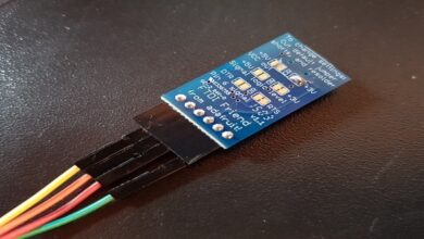
- Arduino Pro Mini (SparkFun P/N 11113; extra headers are available as P/N 00116.)
- FTDI Basic Breakout (SparkFun P/N 09716; this is a programming dongle necessary to program the Arduino Pro Mini.)
- 2 NeoPixel strips (Adafruit P/N 1426 or SparkFun P/N 12661; this is an eight-LED RGB strip.)
- DS1307 RTC Breakout Board (SparkFun P/N 12708; other options are Adafruit P/N 255 or Adafruit P/N 3013.)
- 470 Ω resistor (SparkFun P/N 10969 is a good multipack)
- Enclosure (My enclosure was 85 mm × 55 mm on its largest side and 30 mm deep; find it by searching online for its P/N, WCAH2855. A similar part is the classic 3 × 2 × 1 project enclosure from RadioShack, P/N 2701801.)
- Watchband (Any generic nylon or rubber watchband should do the trick. I used a knockoff iWatch band from Amazon.)
- 9 V battery pack and battery (A standard 9 V connector with wire leads; I’m using Jameco P/N 109154. You can also get the SparkFun P/N 00091 snap connector and cut off the plug.)
- Button (I used a panel-mount momentary button from SparkFun, P/N 11992. The smaller, the better. You can swap out the button for a switch if you want to keep the display going until you turn it off.)
- Screws (I used M2 × 10 mm screws and nuts from HobbyKing, P/N HA0506.)
The small Arduino we use here offers the same Arduino experience without all the bells and whistles so that it will fit in a small enclosure. For instance, you can’t program it via USB, and you’ll need a FTDI Breakout (such as SparkFun P/N 09716) to program it.
Tools
- Soldering iron and solder
- Dremel or similar rotary tool, with cutting and drilling implements
- (Optional) Spray paint
INTRODUCING THE REAL-TIME CLOCK MODULE
It turns out that keeping accurate time isn’t something Arduinos do well. They can keep track of time from second to second fairly well, thanks to the timing crystal built into the board, but they must use their own internal memory to retain this information, so when the memory fills up your clock stops working. Another problem arises when the Arduino loses power—you lose the time and have to reset it when you start the Arduino up again. The solution to these challenges lies in an add-on board called a Real-Time Clock (RTC) module.
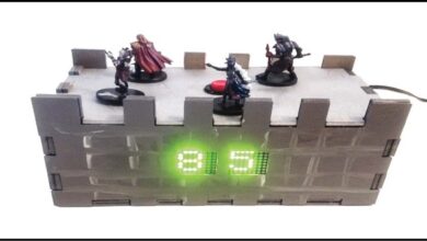
BUILD IT
The watch consists of the electronics and the enclosure that holds them. We’ll work on the two parts simultaneously.
There are 60 entries—one for each minute in an hour—but for the sake of space, I’ve included only three here as examples. The watch displays the hour using the same array, so 7 AM has the same color coding as 7 minutes after the hour. Partly for whimsy and partly for debugging purposes, I made 0 all red. This way you can see when the hour strikes, and it also tells you the code works if you happen to be working on the project around the start of the hour
SUMMARY
Once you complete the physical build and upload the code, your watch is done! It may not be a precision instrument, but it will certainly start a conversation or two.